|
How Electricity
works
ELECTRICAL
In the professional world of electrical wire installations the wiring
is installed neat and orderly manor. If you install the electrical wiring in
straight lines with 90 degree bends you robot will be great to look at and be
easy to work on. Take time to number or mark all of the wires at both ends.
Label The relays and PWM's to what motors they go to. If you install it sloppy,
cutting corners and no ties it will look bad and will be hard to trace problems
down. Take pride in your work and you will be happy to show others what you have
accomplished.
 The most important part or your robot is your electrical connection. Be
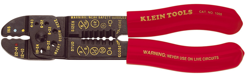
extremely careful of how you crimp your wire connectors. You MUST use a proper
crimp tool (Sta-Kon type tool is the best) Inspect the wire connector and you
will see a seam ( arrow below). This seam MUST be opposite of the knob of the
crimp tool to make a proper crimp. The connector should fit down into the valley
of the tool a the wire should be stripped to proper length and crimped firmly.
The most important part or your robot is your electrical connection. Be
extremely careful of how you crimp your wire connectors. You MUST use a proper
crimp tool (Sta-Kon type tool is the best) Inspect the wire connector and you
will see a seam ( arrow below). This seam MUST be opposite of the knob of the
crimp tool to make a proper crimp. The connector should fit down into the valley
of the tool a the wire should be stripped to proper length and crimped firmly.
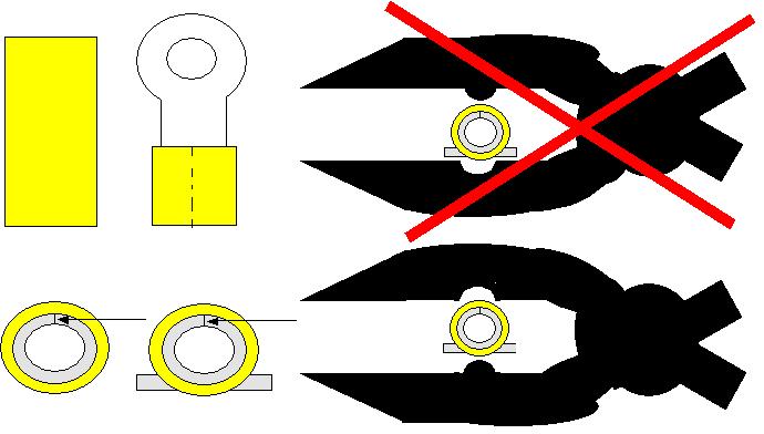
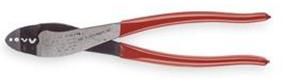
Proper Crimp Tool is on the left, the right is what most people use and it does
not do a good job for crimping wire connectors. It does a great job of cutting
screws but I have seen many connections come loose with that tool.
______________________________________________________
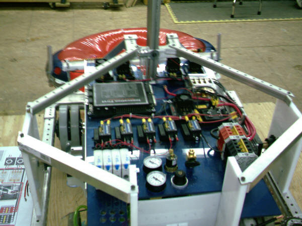
Want your electrical to look great, use solid wire. You can bend
perfect 90's and it won't bend back. This is only used from the fuse block to
the PWM's and relay's. Install quick disconnect wire connectors at
the motors for easy motor replacement. Make a bracket wire trough at 2 - 3
inches above the wiring board for the control wires to run separate from the
motor wires. It's like having a wire rack. Save copies of the PWM's and spike relays in your drawing programs,
and when its time to lay out the electrical it won't take long at all to set up
your board. Plus you can move it around until it fits.
Above is exactly the same lay out of our 2007 robot electrical below.
_________________________________________________________________
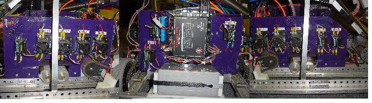
In 2008 we installed the relays and PWM's on one side and ran the wires on
the other side of the electrical board. This made it easier to work on and keep
tract of the wires. Below is a picture of our 2008 robot (the picture is
distorted to make it fit on the page) with the left, back and right side of the
robot.
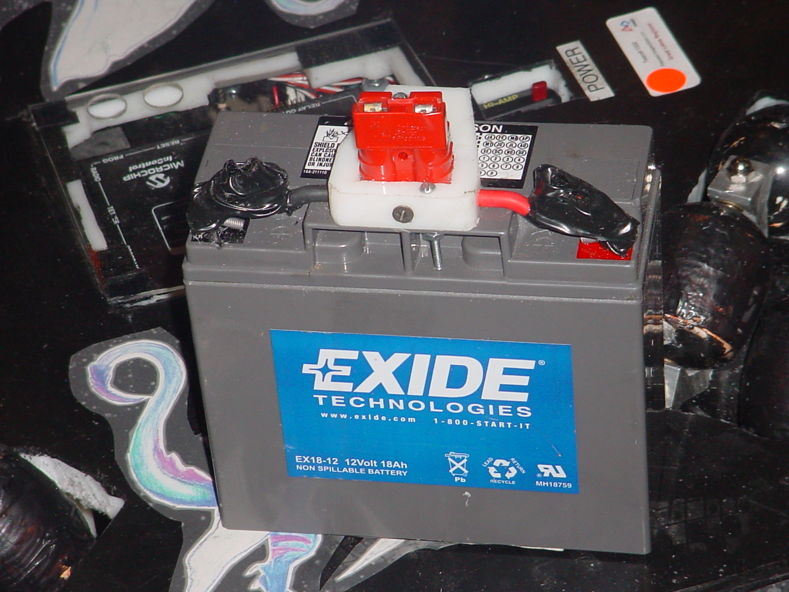
Some thing we do with the battery in make it a modular plug in. All of
our batteries are the same. When it is time to change a battery we just
pull it out and plug in another.
Build a board on wheels with the items from older kit of parts used to help show new students
how
all the items in the kit of parts work. It also can be used to test programming and
parts. The reverse side can be a erase marker board.
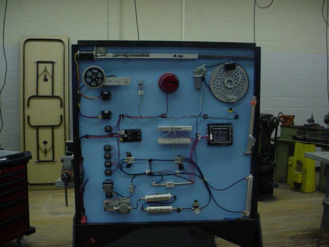
Pneumatics, electric, sensors and controllers can be shown on the board.
|